This is going to be a long one as there’s a fair amount of detail to cover.
Before the Arduino can do anything with the sound card at all, they need to be connected together. We’ll begin by inspecting the sound card, then determine what connections are required, before covering the details of what those connections are actually used for.
Inspecting the hardware
Let’s take a look at the hardware of the Yamaha Audician 32 Plus sound card. First, here’s the component side of the board:
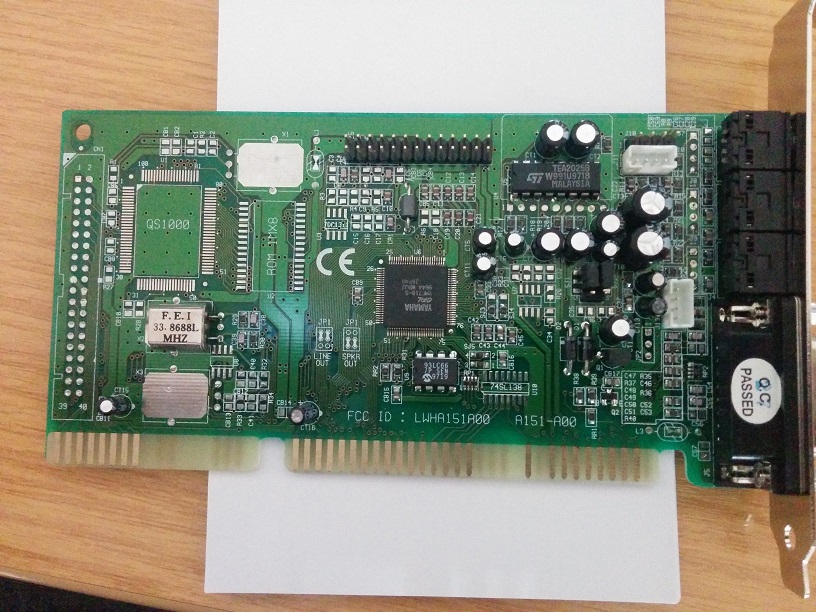
It looks pretty much like any other ISA expansion card for a PC. For those unfamiliar with the layout, the external connectors (joystick/MIDI port, audio jacks) are located to the right of this picture, while the ISA connector is toward the bottom. This is the only part that actually makes an electrical connection with the PC and the most logical choice for working with – the ISA interface is a standard, and documented quite well, whilst the rest of the circuit is not.
The circuitry itself is interesting to look at – researching the markings on the various components reveals what they are for:
- The chip in the middle is the a “Yamaha OPL YMF718-S”. The markings suggest it’s the chip that will be doing the FM synthesis. The fact it has a lot of PCB tracks leading to it suggests that it is the core component of this board.
- Below this is a “93LC66”. This is an EEPROM, connected to some of the ISA pins. I’m not entirely sure what it’s used for in this circuit.
- Toward the left, there’s a 33.8688 MHZ crystal. The nearest capacitors to it are connected to it.
- The “TEA2025B” chip toward the top right is a stereo amplifier.
Mainly to show the other side of the ISA connector, here’s the solder-side of the card:
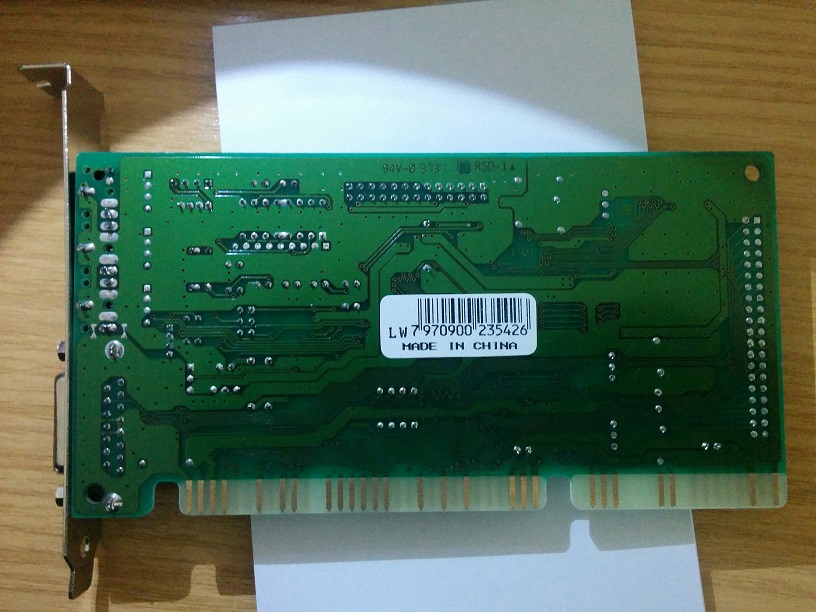
As you can see, the ISA connector has quite a few metal contacts (pins) – understanding what these are for is the first step toward making the card usable with an Arduino Uno.
The ISA connector
As mentioned earlier, ISA is a standard, so there’s some good documentation about it available online. Searching for “ISA pinout”, I found the pinouts.ru website which I found to be a good place to start. There was another site I found (I can’t find the link right now) which mentioned that ISA uses TTL levels, so the voltage levels will be compatible with the Arduino’s digital pins.
There are a couple of things to consider about the ISA connector: Firstly, not all of the metal contacts (pins) are present. As the goal of this project is to make one specific sound card work with an Arduino, we don’t need to care about those pins. Secondly, the PCB has spaces for some optional components that are not present (e.g. “QS1000”, “ROM 1MX8”, a connector and a couple of metallic areas that look like they might be for crystals). Some of the ISA pins might only be used for these non-existent components, so we can forget about those too.
Using a multimeter (in resistance measurement mode) to trace the path between the ISA pins and the components on the board indicates which pins are actually needed. Any measurements that read 0 (or very close to it) have a direct connection. Following the tracks can be a bit difficult where there are a lot of them, so I’d definitely recommend a magnifying glass! This doesn’t work when there is a capacitor between the two points though (just trace the parts of the circuit either side of it).
It’s quite time-consuming but an important step since getting things wrong at this stage will cause problems later on! In the below descriptions, “host” will be used to refer to whatever is interfacing with the sound card – normally this is a PC (or, more specifically, some kind of controller within the PC), but in our case it’ll be an Arduino.
ISA pins used by this card
Let’s take a closer look at the ISA pins. The list of pins may look a bit daunting at first – they certainly did to me, as someone who is still fairly new to the world of electronics. If you have knowledge of the PC architecture some of this may be familiar to you, but in any case I’ll try and explain as best I can.
Here’s the component-side of the card, which has been turned around so that it is easier to compare against the illustration on pinouts.ru:
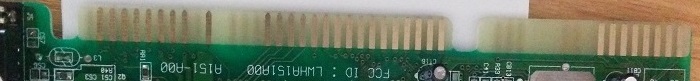
The pins to the left of the notch are A1-A31, while the pins to the right are C1-C18. The PCB is a little translucent, so the pins on the reverse are slightly visible, making it easier to see which pins are missing. There are some slight markings on the connector where the missing pins are, which is also helpful for figuring this out.
Here are the pins that are present on this side of the card:
- A2-A9 = data bits (7-0)
- A11 = address enable
- A16-A31 = address bits (15-0)
- C11-C18 = data bits (8-15) – not connected
The PCB tracks for pins C11-C18 lead only to the connector at the side of the card (which is not present), so those can be ignored.
Now let’s look at the solder-side of the card

The pins to the left of the notch are B1-B31, and the pins on the right are D1-D18. Many of these pins serve similar purposes (e.g. interrupt request) so could be grouped together, but to keep things simple this is just a list from left to right:
- B1 = GND
- B2 = Reset
- B3 = +5V DC
- B4 = Interrupt request #2
- B7 = -12V DC – not connected
- B9 = +12V DC
- B10 = GND
- B13 = I/O write (active low)
- B14 = I/O read (active low)
- B15 = DMA acknowledge #3 (active low)
- B16 = DMA request #3
- B17 = DMA acknowledge #1 (active low)
- B18 = DMA request #1
- B21 = Interrupt request #7
- B23 = Interrupt request #5
- B25 = Interrupt request #3
- B29 = +5V DC
- B30 = High-speed clock – not connected
- B31 = GND
- D2 = I/O 16-bit chip select (active low) – not connected
- D3 = Interrupt request #10
- D4 = Interrupt request #11
- D8 = DMA acknowledge #0 (active low)
- D9 = DMA request #0
- D16 = +5V DC
- D18 = GND
Again, there are some pins that aren’t connected to anything, so we can ignore those.
Now we know what pins are present, it’s a case of working out what they are used for. The pins that aren’t connected to anything on the sound card won’t be discussed. First, we’ll look at the power and ground pins.
Powering the card
First it’s important to be aware of the voltages/currents involved, to avoid destroying components. Supplying a voltage that is too high to the sound card may damage a component on the card. I’ll be powering the card with an Arduino, so it’s important that it can supply enough current otherwise the Arduino could be damaged. Voltages that are too low may cause things to not function, but aren’t likely to pose any harm.
All of these pins are inputs to the card (it’s not intended to produce any power of its own!)
Pins B1, B10 B31 and B18 are all GND pins. When I checked these on this particular sound card with a multimeter, they are all connected together, so we just need to make a single connection to any of those pins to cater for all of them. The ground tracks on the PCB tends to be the most prominent one – they are the large lighter green areas visible on both sides of the card.
Pins B3, B29 and D16 are +5V DC pins. Again, on this particular card these all seem to be connected together so we just connect +5V to any of them to power the card. An Arduino provides +5V, so this is sufficient.
Pins B7 and B9 are perhaps the most troublesome ones – how do we get -12V and +12V? Fortunately B7 doesn’t seem to be connected to anything so we don’t need to worry about -12V. B9 seems to be used for powering the amplifier, which is necessary to get sound output!
Looking at the datasheet for the amplifier chip, it seems the supply voltage can be from 3V up to 12V. So, I tried my luck with feeding +5V into B9 (the +12V pin) – the worst case scenario would be that the chip simply wouldn’t do anything. It does power it sufficiently, and the output seems no different to powering it with +12V. It’s a completely non-standard use of that pin but as the goal is purely to interface with this one card, it saves needing to provide a +12V supply.
Measuring the current draw with a multimeter confirmed that the overall power draw for the power pins is within the boundaries supported by the Arduino (I’ll post the exact measurements at a later date, as I took them a while ago and didn’t make a note of them.)
Reset
This should be kept low, and raised briefly to trigger a reset of the sound card.
Address Enable
This is only high during DMA transfers, which we won’t be using in this project. It should always be low – i.e. just connect it to ground.
Address
The most basic form of communication with PC devices is through I/O ports. These will be used extensively through this project and is the most essential part (besides power!).
Using the address pins, we can basically state what we want to communicate with. It’s analogous to the address written on the envelope of a letter.
The address pins are inputs to the sound card (i.e. the PC powers them, the card itself will never supply power to them). Several expansion cards can be installed in a PC. Most of the connections are common to all of the expansion slots – so, powering one of the address pins will supply power to that pin for all cards. The PC needs a way to communicate with the cards individually, so each has one or more addresses to which it will respond. These must be unique.
The ISA connector allows up to 24 address pins to be present. Each of these represents an individual address bit (high = 1, low = 0), which gives us a range of hexadecimal addresses from 0x0000 to 0xffffff.
This sound card only has 16 address pins however, which gives an address range of 0x0000 to 0xffff. What about the missing 8 pins? They are the highest bits, and the sound card simply doesn’t “see” them. For example:
- 0x002233 would be seen as 0x002233
- 0x112233 would be seen as 0x002233 as the highest 8 bits are ignored
- 0x992233 would also be seen as 0x002233 for the same reason
Using the address pins is a simple case of converting the address to binary and setting the pins “high” or “low” depending on whether a bit is “1” or “0”.
As well as the address, we also need to deal with whatever data will be sent/received.
Data
In conjunction with the address pins, the data pins are where we store or retrieve data to be communicated with the sound card. There are 16 data pins, and similar to the address pins these correspond to a binary value.
On this particular card the high 8 bits are not actually connected to anything, meaning that only the low 8 bits are used. This has a similar effect to the one described earlier – the card simply won’t “see” the high 8 bits.
These pins are a little more complicated than the others, in that they are bi-directional. The host controls them when writing data to an address, and a component/expansion card controls them when the host is reading data from an address.
If data is to be written to the card, we need to set the data pins to high/low states based on the binary value of the data in a similar way to how the address was handled. If data is to be read, we need to instead be prepared to read the state of the pins (i.e. as input).
At this point there is a bit of a problem: The Arduino is capable of switching its pins between input/output states, but you’ve probably noticed we are going to need 24 pins just to deal with the addresses and data! This is a possible issue which we’ll deal with after figuring out the requirements of the card.
I/O read and I/O write
These pins indicate whether data is to be read or written, and are inputs to the sound card. They are “active low”, so both will be high when no reads/writes are taking place.
When the host wants to write some data, it sets the address and data pins and lowers the “I/O write” pin. Several components within a PC respond to this by checking if the address belongs to them – if so, they then act upon the data that was written, otherwise they ignore it. After a short delay, the “I/O write” pin is raised high again (by the host).
When the host wants to read some data, it again sets the address but this time does not control the data pins. It lowers the “I/O read” pin, and the component with the corresponding address communicates an 8-bit value via the data pins (by setting them high/low). The host reads the data by checking the state of the data pins, and raises the “I/O read” pin high again.
The sound card may need time to handle the reads/writes. The above is a simplified version of how ISA communication is supposed to be done – there are BCLK and BALE signals used for timings which this sound card doesn’t actually use, so presumably the card is tolerant of different timings. We can probably forget about those and use some short delays instead.
DMA requests and acknowledgements
DMA (Direct Memory Access) is used by the sound card for playing audio samples. When playing sound, the audio data is stored in the computer’s memory, so the sound card needs a way to get access to it. Essentially DMA negotiates which component has access to the memory.
This sound card can use DMA channels 0, 1 and 3. The DMA pins used for this are B15-B18 and D8-D9.
Fortunately, for the purpose of dealing with MIDI and FM synthesis, this is irrelevant. Since audio sample playback won’t be used, the card won’t be generating DMA requests, so we can just leave the DMA acknowledgement pins floating (i.e. disconnected).
Interrupt requests
The sound card will trigger interrupts for various reasons. An interrupt temporarily makes the CPU stop whatever it is currently doing, and perform some action, before it then goes back to what it was doing before.
Again, this is mostly used for audio playback, where the interrupt will be used to run some code that will load more sound into memory for the sound card to play. However, it is useful in this project for handling MIDI input – when a note is to be played, or a controller to be adjusted, the sound card will trigger an interrupt so that the CPU knows there is some input waiting.
It’s a relatively simple mechanism – the sound card simply supplies power to the relevant interrupt pin to get the attention of the CPU and stops supplying power when it no longer needs attention. In the case of an Arduino we could just hook this up to one of the input pins and keep checking it in a loop and take action when it the input is high. It’s not as efficient to do this, but it’s suitable to begin with. The ATmega chips used by the Arduino do support interrupts so we can consider using those eventually.
Looking at the pins, it’s possible to see that the sound card uses interrupts 3, 5, 7, 10 and 11. However, not all of them are supported for MIDI input. We’ll come back to this later on as we don’t need interrupts to get the FM synthesis part working.
Summary
The sound card’s voltages are compatible with the Arduino, but the number of pins required to use the card exceeds the available I/O pins on the Arduino Uno (16 pins for the address, 8 for the data, 2 for I/O control, possibly others…)
FM synthesis and MIDI do not use the DMA request and acknowledgement pins and can be ignored. We may wish to use an interrupt to handle MIDI input at a later stage but for now we can ignore that too.
Since this project is intended to control this one specific sound card, we can take some shortcuts that will deviate from the ISA specification (such as timing handling, providing +5V on the +12V connector for the amp chip, etc.)
Before we can actually get the Arduino involved with this, we need to work out how to get control of all of the I/O pins required. There are components that can help with this, which will be covered next time.